Friday, 9 November 2012

Line Follower

Here is a small clip showing the Line Follower performance and the LeJOS code associated with it. The robot here is the small car which is built using small booklet provided with NXT kit. The LeJOS firmware for NXT can be downloaded and installed on the NXT brick from LeJOS NXJ 0.9.1. The design of my Java program is heavily influenced by the Line Follower in the book "Programming Lego Mindstorms with Java" by Giulio Ferrai et all. The actual algorithm to follow the line is influenced by Jacek Fedorynski's Line Follower NXC program. The LeJOS program has four classes: LFJfedor, Cruiser, LFUtils and LineValueHolder. The LFJfedor class contains the main method and is the starting point of the program. This class initializes the light sensor and calibrates the sensor for Black and White values in its constructor. The black and white values are stored inside a Java Bean called LineValueHolder. LFJfedor class also starts the thread Cruiser.  The Cruiser class has the algorithm to follow the line, given the calibrated black and white values and the light intensity at any given point in time. LFUtils class calculates the average light intensity over 20 samples, at any given point of time. The average over 20 points is calculated in order to smoothen out the spikes in the light intensity (if they exist). Let me explain some of the program details below.  

In order to calibrate the threshold for White, the NXT brick beeps twice. It prints the message "white" on the screen of the NXT brick. The user is supposed to keep the light sensor on the White part of the line follower chart and press the ESCAPE button. This process will record the White light intensity in the Java Bean  LineValueHolder. Similarly, record the Black value when the NXT beeps twice again. It prints the message "black" on the NXT screen. The user is supposed to keep the light sensor on the black strip of the line follower chart and press the ESCAPE button. This process will record the Black light intensity in the Java Bean LineValueHolder. Once the White and Black intensities are recorded, the Line Follower program works as follows:

  1. The Line follower follows the edge of the line where the threshold value is (Black + White)/2
  2. The instantaneous value of the light is calculated by averaging over 20 light samples
  3. The B Moter and C Moter is powered in proportion to the difference between the threshold and the instantaneous value of light (defined by the variable "color")
  4.  The initial value of power = 22 and the constant multiplier 50 requires few attempts to be set correctly in order to follow the line, in a certain speed


I wish you enjoyed the article!

Tuesday, 14 August 2012

Maximize Sound

This is a small program which I have come up with, to learn about sound sensor and data wiring in NXT. Here the robot's "roaming boundary" is decided by decreasing sound level. That means, the robot tries to remain within the boundary where raw sound level drops by 100. The robot should move away from the sound source only until the sound level drops by 100. After which the robot is supposed to take a U turn and move more closer to the sound source. Let's go through the NXT-G program to achieve this goal. Please click on the below image in order to maximize it and take a look at the NXT-G program. Alternatively, you can also download the .rbt file and check out the comments to understand the NXT program.


Let me explain all the blocks to you one by one.

  1. Drag and drop the Sound Sensor block on the sequence beam in the Work Area
  2. Drag and drop the Variable block and put it next to the Sound Sensor block. Name this variable as maxsound
  3. Stretch a yellow wire from the Sound Sensor Block to the input of the Variable block. This will initialize the maxsound variable with the sound sensor sample
  4. Drag and drop the Motor Block on to the sequence beam and configure it using the configuration panel to move the motors B and C for two seconds
  5. Drag and Drop the sound sensor block to collect the sound sample (after forward movement of the robot in step 4)
  6. Drag and drop the Variable block and put it next to the sound sensor block. Name this variable as sound
  7. Stretch a yellow wire from the Sound Sensor Block to the input of the Variable block. This will initialize the sound variable with the sound sensor sample
  8. Drag and drop the variable block maxsound on the sequence beam, and put it next to all the previous blocks
  9. Drag and drop the variable block sound on the sequence beam, and put it next to all the previous blocks
  10. Drag and drop the Compare block and put it next to all the previous blocks
  11. Stretch yellow wires from maxsound and sound variable blocks and make them as inputs to the Compare block
  12. Drag and drop a Switch block and place it on to the sequence beam
  13. Draw a data wire from the output of the Compare block to the input of the Switch block. If sound is greater than maxsound, the upper part of Switch block will be executed. If the sound is lesser than maxsound, the lower part of the Switch block will be executed
  14. If sound is greater than maxsound, copy the value of sound variable in maxsound variable. That will keep maxsound variable updated with the maximum value of sound so far. Do this by dragging and dropping the sound and maxsound variables on to the upper part of the switch and stretching a wire from sound output to maxsound input 
  15. Next, find the difference between the peak sound reading and the latest sound reading. Check if the difference between the two sound levels is greater than 100. We can achieve this by dragging and dropping the sound and maxsound blocks on the sequence beam and putting the Maths block next to them. Stretch the yellow wires from the sound and maxsound variables to the Maths block input. Then stretch a yellow wire from the output of the Maths block to the Compare block to check if the difference between sound and maxsound is greater than 100
  16. Drag and drop a Switch block and place it on to the sequence beam. The Switch block has two parts, upper and lower. The upper part gets executed if the input is True. And the lower part gets executed if the input is False. Drag a wire from the output of the Compare block to the input of the Switch block. If the output of the Compare block is true (if the difference between sound and maxsound is greater than 100), the robot will take a U turn. This can be achieved by placing a Motor Block in the upper part of the Switch with only a single Motor on. In my case its a C motor 
  17. Place the steps from 4 to 16 in a loop which will execute them again and again forever.


In Essence the entire algorithm of bringing back the robot after reaching a point where sound level drops by 100 is as below:

  1. Keep the maxsound variable updated with maximum sound value so far
  2. Keep comparing the maxsound with the latest sound sample (The latest sound sample will keep reducing as and when the robot moves away from the sound source)
  3. If the difference between the maxsound and latest sound sample is greater than 100, make the robot take a U turn
  4. If not, keep the robot moving forward

Please take a look at the functioning of the robot in the below video clip. 


Hope you enjoyed the article!
Please go through the below article to know about Lego data wiring in detail.

Tuesday, 31 July 2012

Move Forward Until Occurrence Of Black Boundary

Now, let's give the robot a restricted space to move. The robot here is the small car which we can build by following the small booklet provided with the NXT kit. Let us draw a black line around the robot's space, to identify its boundary. When the robot touches the black line, it is supposed to take reverse and try another time to escape the boundary. The question is how the robot notices the black boundary? Yes, we have to use a Light Sensor. Light Sensor measures the light intensity in a room and converts it into meaningful values. It passes the values to the NXT. NXT can then use a calibration program to convert the light sensor values into minimum and maximum. Calibration process allows the sensor to get the readings within an acceptable range which then makes programming easier. Please take a look at below video to see the different ways provided by NXT to calibrate the light sensor. You can go ahead with any one way and calibrate your sensor. 


Let's start to write a program which then uses the calibrated values to understand robot's boundary. It is going to be a two-step program. 
  • Keep moving forward until the robot hits a black boundary line (Light Sensor helps to identify the black boundary line)
  • When robot hits the black boundary line, drive backwards for 2 seconds
Keep repeating the above steps and observe robot’s behavior. Now let's program these steps with the help of NXT-G programming language. Drag and Drop the Switch Block from the left Palette to the Work Area. This Switch has two parts, the upper part and the lower part. The upper part controls the unusual behavior of the robot. The lower part controls the default behavior of the robot. Now, click on the Switch and see its configuration panel at the bottom of the screen. Please select the below configuration fields and their values.

Control - Sensor
Sensor - Light Sensor
Port - The port number where light sensor is connected (in my case port 3)
Light - Greater than 20 (which means when the light intensity exceeds 20% of the maximum value)

This configuration means that the light sensor will consider darkness when the illumination is about 20% of maximum and it will consider brightness when the illumination exceeds 20% of maximum. Please take a look at the below figure to see my configuration of Switch Block. 


As a next step, let us drag and drop a Motor Block in the upper part of the Switch. This Motor Block will get activated when the robot finds brightness. Click on the Motor Block and see its configuration panel at the bottom of the screen. I would like the robot to keep moving forward until it is in brightness. I selected the motors B and C in order for robot to move forward for unlimited duration. Keep rest all the configuration the same. Please see the below configuration of my Motor Block on detection of light. 


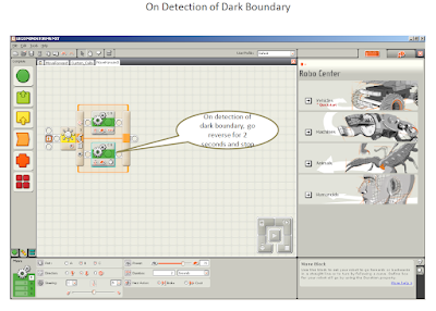
Next, let us drag and drop another Motor Block in the lower part of the Switch. This motor block will get activated when the robot encounters the black line. Click on this Motor Block and see its configuration panel at the bottom of the screen. Since I would like the motor to go reverse for 2 seconds on occurrence of the black boundary, I have selected Motor B and C of the robot, with Direction field to be reverse and Duration to be 2 seconds. I kept rest all the fields to be default. Please take a look at the figure below to check my configuration of the Motor Block. 


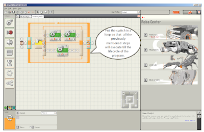
Further, configure the robot to keep moving between light and dark indefinitely. In order to achieve this please put the entire configuration above in a Loop. Click on this loop and see its configuration at the bottom of the screen below. Please select the Control field to be Forever. Please see my final NXT-G program below. 


Download this program on the NXT brick and see the movement of the robot. The below video clip captures the movement of my robot. 


As seen in the video, the light sensor is mounted on the front part of the robot, about 2 mm above from the surface and has a red light emitted out of it. The robot touches the black boundary line twice and then reverses back for 2 seconds. 

For learning about Lego NXT blocks please visit the site below. 

Hope you enjoyed the article!


Monday, 23 July 2012

Roaming With Ultrasonic Sensor

In the last post, we used the touch sensor to detect an object. However, touch sensor responds on colliding with an object. Colliding could harm our robot (The robot here is the small car which we can build by following the small booklet provided with the NXT kit). So, let's use an ultrasonic sensor. Ultrasonic sensor detects an object when it is at a certain distance from the object. Thus ultrasonic sensor gives a much cleaner object detection. The robot follows the following rules while moving around in the world. 
  • If there is no object in 50 Inches distance in front of the robot, the robot keeps moving on 
  • Once an object is detected the robot takes following two steps
    • Get the robot reversed for 2 seconds
    • Turn the robot away from the obstacle by turning the motor 180 degrees
Now, let's take a look into the NXT program to achieve the above behavior.

At first, drag and drop the Switch Block from the left palette to the work area. The Switch Block has two parts. Upper and Lower part. The upper part gets enabled when the object is detected within 50 Inches limit. The lower part gets enabled as a default function of the robot. Click on the Switch and you will get to see its Configuration Panel at the bottom. In the Configuration Panel, please select Control field to be Sensor. Further, choose Sensor field as Ultrasonic Sensor. Select the port where Ultrasonic Sensor is attached to the NXT brick. In my case it was Port-4. Select the Compare field to be of Distance less than 50 (it is a little mathematical expression) and its unit to be Inches. That means the ultrasonic sensor will detect an object if it is in the range less than 50 Inches. Please take a look at my configuration in the below figure. 


Now let us program the first step on object detection. The car gets reversed for two seconds. In order to achieve that please drag and drop the Motor Box on to the Work Area within the upper part of the Switch. Click on this Motor Box. The Configuration Panel of the Motor Box will appear at the bottom of the screen as shown in the figure below. I am using Motor B and Motor C to drive the car. So I have selected the motor options accordingly. Since I want to drive the motors reverse, I have chosen the Direction option to be reverse arrow. Choose the Duration to be 2 seconds. Keep rest all the options as default. 


Let's program the second step of object detection, which is to take a turn to move away from the object. To do this, please drag and drop the Motor Box from the left Configuration Palette to the Work Area, just next to the previous Motor Box. This will make the previous and the current actions execute sequentially. Click on this Motor Box to get its corresponding configuration at the bottom of the screen. As shown in the below figure, this box is configured to take a turn to move away from the obstacle. To take a turn (in place), enable a single motor, in my case Motor B. Please select the Duration option to be 180 degrees. That means the servo motors of the robot will be programmed to take a 180 degrees turn. Please remember, the servo motor turn is very different from the 180 degrees turn in the physical space. To know more about Lego NXT Servo Motor design, please visit 


Now configure the Motor Box to take a default action of moving forward, when there is no object in the limit of 50 Inches in front of the car.  Place this Motor Box in the lower part of the Switch box as shown in the below figure. Click on the Motor Box to get its configuration at the bottom of the screen. Since we want to keep the motor freely moving forward in the default condition, we will select the Motor B and Motor C with the Direction to be Forward Arrow. The Duration is selected to be Unlimited and rest all the configurations are kept as unchanged. 


As the last step, we need to put the Switch Box in a Loop, which will allow us to run all the configurations inside the loop forever. Please drag and drop the Loop from the left palette and place it around the Switch Box. Click on the Loop to see its configuration at the bottom of the screen. Please select Control field to be Forever. See the figure below for my configurations. 


Further, we will download our program on the Lego NXT brick and see the results as shown in the below video. 


You can see that every time when the obstacle is encountered, the robot goes reverse for 2 seconds and then take a turn of 180 degrees in Motor Space. In my case, at first the car encounters my hand in front of the ultrasonic sensor, so the car goes back when I switch the Lego NXT Program ON. Then the car encounters the wall. The robot can not turn away from the wall in one go. So you will see that there are multiple "reverse and turn" actions to move away from the wall. At the end, the robot encounters a soft toy. For some reason the Ultrasonic Sensor is unable to detect the fabric of the toy. May be, because the robot approaches the toy from a different angle or because the ultrasonic sensor is unable to detect the fabric itself. 

I hope you enjoyed this article!

Thursday, 19 July 2012

Roaming With Touch Sensor

Now, let's take it a little further and set the car robot free to roam around. The car in this article is built using the small booklet which is delivered with the Lego kit. Now think, what if the robot collided with an obstacle! There comes the role of a touch sensor. Touch sensor gives the robot a sense of obstacle on its path. The sensor communicates this information to the NXT. NXT then decides what action to take, if an obstacle is present. So, lets take a look into the NXT program to observe the robot's behavior in the free world! In this project, the robot handles two distinct situations. 
  • If there is an obstacle present on the path, (as realized when Touch Sensor is pressed), do the following
    1. Make the robot go reverse
    2. Take a turn to move away from the obstacle
  • There is no obstacle, (as realized when Touch Sensor is in released or bumped state)
    1. Keep the robot moving forward
Let's program for the above two situations now. Drag and drop the Switch block from the left palette. This block performs certain actions when specific conditions are met. You will observe that there are two parts of the Switch box, the upper and lower one. 


Click on the Switch Box to see its configuration panel at the bottom of the screen (Please check the above figure). As per the configuration, please make sure that the sensor is selected to be Touch Sensor and the sensor is connected to port number 1 of NXT brick. The action is selected to be pressed. That means we have configured the upper part of Switch box if touch sensor is in pressed condition and below part of the Switch box is configured for sensor to be in other conditions, which are released or bumped. Drag and Drop the Motor Box from the left palette, over to the upper part of the Switch Box. Click on the Motor Box to see its configuration panel at the bottom of the screen. Configure this panel to make the car go reverse, when the obstacle is found and Touch Sensor is pressed. Please power on the motors B and C to go into reverse direction for 2 seconds. Keep rest of the configuration as it is. The below figure shows the configuration panel for the motor box for my car.     


Drag and drop another Motor Box in the upper part of the Switch Box, and place it next to the previous Motor Box (which we used for reversing the car). Click on this box and see its configuration panel at the bottom. Configure this Motor Box to take a turn. In order to take a turn, powered on only one motor (in my case Motor B) in reverse direction for 1 second. This will make the car move away from the direction of the obstacle. Please check the below figure for the configuration of this second Motor Box.   


Now drag and drop the third Motor Box in the lower part of the Switch Box, which will function in all other states of the touch sensor except pressed state, for example Bumped and Release state. This box will keep the car moving forward in the default conditions. Please check the figure below. 


Click on this third Motor Box and check its configuration panel below. I have configured it for my car to power on the Motors B and C to move in forward direction for unlimited duration. Now is the time to put the entire switch in a loop which will help the car to execute all previously defined steps forever. Please check the figure below. Click on the loop and we get the Configuration Panel of the loop at the bottom. Please select forever, in order to keep the car moving for its entire lifecycle. 


Download the program on to NXT brick and observe the movement of the robot. I have recorded the movement of my robot in a small clip below. 


As you can view from the clip, the robot encounters three obstacles on its way. On every occurrence of obstacle, the robot reverses, then it makes a turn and then start moving forward. Hope you enjoyed this article!


Sunday, 15 July 2012

Return To Origin

Let's move on and make the robot move little more distant. The robot here is the small car which is built using small booklet provided with NXT kit. Let's make it a point that the robot will come back from where it has started. So, I have made the robot move for 5 seconds, make it take a U-turn and return to its origin. Let's take a look at the steps that we are going to follow. 


I will program the three steps mentioned above using NXT-G programming. Let's program for the first step Go Forward.


As shown in the figure above, drag and drop the Motor Block from the left palette to the Work Area. Click on the Motor Block and check its Configuration Panel in the bottom. Since we want to program it to move forward, we need to move both the rear wheels with the same speed for the same time. In my case, the rear wheels were powered on by Motor B and Motor C. So I have checked the ports B and C in the Configuration Panel. I want to drive the motor for 5 seconds, so I have specified the Duration to be 5 seconds. Next step for the robot is to take a U-turn (either from the left or from the right side). In order to do this, please drag and drop the Motor Block to the Work Area in succession with the first block shown in the above figure. The NXT-G program now looks like below. 


Please click on the second Motor Block and check its configuration at the bottom. In order to take a U turn, stop one of the rear motors and power-on the other motor. In my case I am powering on the C Motor and stopping the B motor. That will make the robot take a turn. To take a complete U-Turn the motor has to be rorated through 810 degrees (We came up to this number through multiple trial-and-error). Keep rest of the configurations as they are. And let's move to configuration of the third step, which is Come Back to The Origin. The NXT-G program now looks like below. 


As you can see the program now has three Motor Blocks in succession which correspond to the three steps which are required to return back to the origin. In order to configure the third Motor Block, click on to the block and check its Configuration Panel at the bottom. I have powered on both the rear motors for 5 seconds of duration as shown in the above figure. Now it's the time to run the NXT-G program and see the output in the below video. I have used the Line-Follower paper just as a baseline in order to get the correct start and end point of the robot. 


Friday, 13 July 2012

Spinning Motion


Recently I have started understanding Lego Mindstorms NXT programming. As and when I update my learnings, I thought of sharing it with you. Please find a small program below in NXT-G, to spin the Robot in a clockwise direction. 


The robot here is the small car which is built using small booklet provided with NXT kit. In order to begin programming, drag and drop the Motor Block from the left palette to the Work Area. Click on the Motor Block on the Work Area and check its Configuration Panel in the bottom. Pick the appropriate port from the bottom Configuration Panel which is used to stop the right motor and power on the left motor. In my case the Motor Port to power on the left motor was Port C. Specify the Duration for which the motor needs to spin. I am spinning it for 5 seconds. Keep rest all the configurations as default. Please view the below video to check the output of the program.