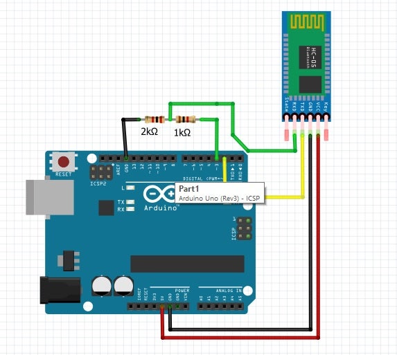
- Connect 5v to 5v
- Connect GND to GND
- Connect Tx to pin 2
- Connect Rx to pin 3 and GND through resistors (2k and 1k) as shown below
- EN and state pins remain hanging
- Remove the 5v connection to HC-05
- Remove the connections to Pin 2 and 3 of arduino
- Connect the arduino to PC to power on using USB
- Upload the sketch below
#include <SoftwareSerial.h>
SoftwareSerial BTserial(2, 3); // RX | TX // Connect the HC-05 TX to Arduino pin 2 RX.
// Connect the HC-05 RX to Arduino pin 3 TX
char c = ' ';
void setup() {
Serial.begin(9600);
Serial.println("Arduino is ready");
Serial.println("Remember to select Both NL & CR in the serial monitor");
// HC-05 default serial speed for AT mode is 38400
BTserial.begin(38400);
}
void loop() {
// Keep reading from HC-05 and send to Arduino Serial Monitor
if (BTserial.available()) {
c = BTserial.read();
Serial.write(c);
}
// Keep reading from Arduino Serial Monitor and send to HC-05
if (Serial.available()) {
c = Serial.read();
BTserial.write(c); }
}
- Keep holding the button on HC-05
- Connect 5v to 5v, the HC-05 will go into AT mode
- Release the button on HC-05
- Reconnect hc-05 to pin 2 and 3
- Execute the following AT commands through serial monitor (make sure the baud rate is set to 9600 and line endings is set to be "Both NL & CR")
AT+ROLE=0
AT+POLAR=1,0
AT+UART=115200,0,0
- Remove the USB connection to arduino
2. Setup hc-05 with PC
- Power arduino with AA cells (4.8 v)
- From the Control Panel select Add a Device.
- Add the Bluetooth module.
- Select enter pairing code option.
- Enter "1234" for the pairing code.
- At the Add a device success window, click Close.
- Device ready to use. The OS will create two serial COM ports associated with the device. Always use the one with the lower number.
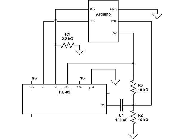
3. Solder a jumper onto Bluetooth module on Pin 32
4. Build ONLY the RESET pin connections and change pin 2 and 3 connections to pin 0 and 1 respectively as shown below - keeping rest all the above circuit the same
Hello all, below is our first robot (A line follower), using actual electronics components. So far we were working with NXT and EV3 Line Followers, where electronics was almost hidden in the brick. We used a DIY (Do It Yourselves) kit from the local robotics store. The DIY kit looks like below.
It consists of the following components
We also purchased a switch to connect and disconnect the batteries from the rest of the circuit. Our switch looks like below.
I am listing the specifications for the switch below just for reference:
We purchased two Infrared Object Sensors as below
The other electronics components which we used are:
1. Arduino microcontroller 2. L293D - V1 motor driver shield
3. Four AA batteries
We assembled our car as per the instructions provided in the DIY kit. We assembled the circuit for Line-Follower as shown in the below circuit diagram.
I am listing down the steps of the assembly below.
We stacked Motor-Shield over Arduino-Uno.
The AA batteries are placed into the battery holder provided with DIY chassis.
The red wire of the battery holder is soldered to I end of the switch
The black wire of the battery holder is connected to the ground of the shield
The O end of the switch is connected to +M of the shield.
The black and red wires are soldered to both the yellow DC motors (provided with the chassis) as shown below. The wires are then connected to the M3 and M4 ports of the shield. The polarity of the connections matter, in the sense that if we reverse the connections, the motors will rotate in opposite directions. As a result, our car moves in opposite direction. So we need to first decide which way we want our car to move and then make the connections.
To know more about the Arduino-L293D stacking and about the motor connections, please refer to video stacking-and-motor-connections. It is a great source of information.
We mounted both the infrared sensors below the car, such that they will be closer to the ground and hence near the black line. Hence if you see the video, you will not be able to see the IR sensors on top of the car. They get somewhat hidden. We connected Vcc and GND of both the Infrared sensors to +M and GND of the shield respectively.
We connected the OUT pin of the LEFT infrared sensor to pin 13 of the shield.
We connectedthe OUT pin of the RIGHT infrared sensor to pin 2 of the shield.
NOTE: With Left and Right, I mean physical mounting of the sensors on the car on the Left and Right side respectively (in the below portion of the car). The Left sensor will track the line when the robot moves anti-clockwise. While the right sensor will track the line when the robot moves clockwise. The video below shows only the clock-wise movement. In order to move the robot anti-clockwise, you will have to physically place the robot pointing to the anti-clockwise direction. Most probably, the robot will follow the inner edge of the line, when it follows the line anti-clockwise (As you must have observed that the robot follows outer edge of the line when moving clockwise). However, you might have to try and confirm it.
Before putting the IR sensors to use, we need to calibrate them. Please use the instructions in the site IR Sensor Calibration For Line Follower. This site lists the instructions for line-follower as well as object detection. Make sure you follow the instructions for line-follower. Let me note a couple of points, this site does not mention.
It mentions making of the connections after the calibration section. However, we have to make sure that we will make the connections, before the calibration. That will help the LED glow based on the potentiometer setting and we can visualize it.
It mentions the turning ON and OFF of signal LED. However it does not show where the signal LED is located on the IR sensor board. As one might think either one of the black or white LED might be a signal LED. However, that is not the case. The signal LED is placed on the board. It lights ON or OFF based on the placement of the sensor on the white surface or the black line respectively.
We have also used an IR receiver to receive signals from the remote control. Below is a picture for our remote control as well as the IR receiver. Please refer to the video at IR Receiver Connections With Arduino to get the IR Receiver connected with Arduino (in reality the shield) and receive signals from the remote control.
This is the first version of our line follower program. Slowly, we have to modify it in such a way that, we do not see / feel the jerks. The current programming logic is, if the robot is currently on white surface, turn the motors to bring it on black surface. And if it is currently on the black surface, bring it on the white surface. Therefore, the robot moves in a zig-zag manner.
We used Arduino IDE to develop the code. line_follower.cpp is the main file, which uses Arduino.h, WProgram.h as built-in libraries those are must for the program to function. The IRremote.h is a library module which needs to be imported for the program to function remotely with a remote control. Now, I will go into the details of only those header files and cpp files which are developed by me. Those are listed above. The line_follower.cpp has the while loop which keeps checking if the STOP button is pressed over the remote control. If the STOP button is not pressed, the car gets the reading from left and right IR sensor. The logic then decides the action to be performed based on the inputs scenarios: There are four distinct scenarios here:
Left = 1, Right = 1
Left = 0, Right = 0
Left = 1, Right = 0
Left = 0, Right = 1
In each of the scenario, the program takes action to rotate motors in certain way. After which when stop button is pressed, the car stops.
I applied this concept (for Lego Mindstorms Robot), to Arduino robot. I applied the "Line follower" formula given in the above article, to "wall follower". As per the above site, the "Line Follower" formula is:
error = LightValue - offset ! calculate the error by subtracting the offset
integral = integral + error ! calculate the integral
derivative = error - lastError ! calculate the derivative
Turn = Kp*error + Ki*integral + Kd*derivative ! the "P term" the "I term" and the "D term"
In case of Wall Follower, "offset" is the setpoint (The constant distance which we desire to keep between wall and robot). The LightValue (the instantaneous light sensor readings) is substituted by instantaneous ultrasonic sensor readings. The "Turn" variable can return the pwm value for arduino to vary the speed of the motor. But in my case, I am using "Adafruit Motor Shield V1" (https://learn.adafruit.com/adafruit-motor-shield/overview) which is stacked on top of arduino. This shield drives the two dc motors. I have downloaded and imported its libraries. These libraries allow us to control the speed of the motor without getting into PWM details. The speed can vary between 0 to 255. In my case, I am directly controlling the speed with the PID formula. That is
Just for information: For the results in the below video, I am applying three PIDs. One for right turn, One for left turn and One for straight line. So I had to keep adjusting 9 parameters to tune it for patrolling the room. I began with specifying kp = 1 for straight drive. Then slowly keep on increasing or reducing kp. The robot oscillates but it follows the wall. Then I applied kd to reduce the oscillations and stabilize the robot. I have put some ki value (which is really small) just for experiment sake, but it is not causing any harm to robot. In future, there might be a possibility to calculate the PID tuning values through Neural Network or something. But I have not explored that possibility until now.
As far as my observation goes, the PID constants depend upon the geography of the surrounding area. For example, if you have 3 right and 2 left turns in the room/lab, then you have one set of PID constants. However, if you change the room where you have 2 right and 3 left turns, then you have totally different set of PID constants. The "bottom line" is, you will "have to" tune the PID for your requirements. I would suggest the following approach for tuning:
Just focus on getting the robot follow a straight wall first. No turns. Remove the code for right/left turns and apply it to the robot.
Once the straight wall is followed properly, introduce left turn. Add the left turn code.
Introduce right turn at the end.
Some thoughts about left turn: As per my observation, the left turn of robot totally depends on the following
PID parameters
The voltage
The speed of the robot.
To reduce the speed of the robot: You can try reducing the speed at the turn. In stead of using 128 as a reference speed, use 64 as reference speed. So the equation will be
As per my observations: When we change the primary speed, we have to change the PID tuning parameters (Kp, Ki, Kd) also. Only then it works well. If you reduce the primary speed to half (64), try to divide Kp, Ki, Kd to half and see the changes in the movement. After observing the changes, take your own decision (regarding tuning), as per your intuition.
Voltage Variations: Regarding the "voltage", it slowly reduces, as and when you experiment with the robot. This impacts the way the robot turns.
I am sharing a video of my wall follower robot which is able to patrol all over the room successfully. It starts from the sofa and ends up near the sofa. The right turn seem to be drastic. Other than that everything seems ok. This is all using PID controller. It took nearly 500 experiments (with different PID values) over last 1.5 months to reach this stage. Each experiment took almost 10 min. This robot is very sensitive to voltage changes. If the voltage is between 5.3V to 5.6V, it works correctly. Otherwise not. I will need to design a voltage regulator to maintain constant voltage to the microcontroller and sensors. Hope you will enjoy the video.
1. Sometimes, the robot takes a U turn instead of taking a left turn .. Why?
Answer: It is because the "correction" value overflows. When I implemented the if statement, to truncate the correction to 127 as below, the problem had vanished. I had added the following statements to resolve this issue:
if(correction > 0 && correction > 127)
correction = 127;
if(correction > 0 && correction > -127)
correction = -127;
Further to correctly follow the wall after any turn, I had inserted "initializeWall" function at appropriate places. Make sure that is added in the code properly.
Lastly, you might need to change the PID values for straight line slightly to take a left turn. As usual begin with kp, the change kd then change ki.
2. A question about the code. My robot sees the obstacle in front of him but drives straight into it, it doesnt turn, what can cause this problem?
Answer: When my robot sees an object in front, it takes a right turn. I have put some extreme tuning parameters (like MY_Kp_Front=40 and MY_Kd_Front=20) to make the robot take a right turn. However, the same tuning parameters might not work for you, because of the "weight" of the robot and the "voltage" supplied to the robot. Here, you have to play with the turning params and come to a decision.
My robot patrols the complete room, only 30% of the time. For rest 70% of the time, it collides at one turn or the other. I am still working on this inconsistency. Meanwhile, I feel that, there has to be some "fall back mechanism" for the robot to complete the wall following. (For Example: when the robot collides at a turn, you can make it "take reverse for few seconds, change the angle and move on".)
3. Did you guess what parameter is responsible for the first move from starting position? If you dont know what I mean I will try to explain below: When I start the robot and put it in my target distance from the wall (which is 12cm) it goes nice and straight, but when I put closer or further from the wall the robot drives into it. Increasing Kd should help?
Answer: If the robot crashed into the wall or moved away from the wall (when kept little away or closer to the wall), that means error is getting amplified a lot in the beginning. Try reducing Kp (first) and increasing Kd (second) and both (third).
4. Isint a negative number of motor speed a problem? For example if I set motor speed to "-40", will it see it as 40?
Answer: How the motor handles negative numbers, totally depends upon the implementation of its library/driver. For me, I am using Adafruit Motor Shield. It stores the speed value, in a unsigned int (0 to 256). Hence I have chosen a primary speed to be 128 and applied the PID correction on top of it. If the PID value goes more than 127, I have truncated it to be 127. Also, if the PID value is less than -127, i have truncated it to be -127. That will make "primary speed + correction" to range from 0 to 256.
5. My robot turns left too early and he ends up stuck in the wall like this:
Answer: You try changing the PID coefficients for Left turn. If you are following my code, I have a different set of coefficients for Left turn. Try changing the derivative coefficient (Kd) for left turn. Decrease the Kd value and see the difference. In my code, the below "Correction" equation has the PID coefficients for left turn.
//PID for left turn
int speed = 2.5 * WF_Error + 8 * WF_Derivative;
In the above equation, the Kd value is 8. Reduce it.
6. I changed from 6V (which was not enough) to 9V. After doing that I had to change speeds of course, because 255 on Maximum was too much. But after doing that my robot freaked out at left turns again. It is turning wrong when there is a short wall after obstacle. Example in the picture:
so the red line is the path of my robot. Looks like it has no time to settle down after bigger error. I tried to change Kd for left turn, I tried to lower speed more. I have no idea how to solve this problem.
Answer: I also observed that, there is a right turn, followed by an immediate left turn. The right turn PID might be affecting left PID here. Can you try making the right turn PID values little lower (if you have made them drastically high).
Hello all, please find here our version of Omni-Biped (one creation from Daniele Benedettelli's book 'Creating Cool Mindstorm's NXT Robots'). We have also implemented the exact version of Omni-Biped given in the book, which can be found at the location Omni-Biped. So let me list the changes which we have made in our version of robot:
We have implemented our own additional hardware of the robot, which can be considered a taller upper part of the body
We have also implemented the head, which can be moved through 180 degrees, close to human head
We have implemented additional software which will move the head through 180 degrees
Rest of the functions are as per the original version of the robot, which are: We can move the robot forward, backward and make it take a turn. It also moves its head around while turning. All this is done with a small Java program with LeJOS NXJ. Please find the Video clip of the robot's performance and the corresponding Java program below.
Let me explain the LeJOS program a little. This is a simple program compared to the program inspired by single-Task C program from the book, which I implemented in LeJOS. We have kept this program as simple as possible, just because it is made for children of age 10 to 12. This program does not have the logic for re-align legs in the beginning or after taking a turn. However, we realized that without re-aligning legs, the robot functions almost similar to its original version. That might be because of its solid mechanical assembly. If we set both A and B motors forward, the robot moves forward. If we move the motors backwards, the robot moves backwards. If we move one motor forward and the other backwards, the robot turns. We have used motor C to rotate the head. the head rotates in 90, -180 and 90 degrees sequence. This sequence brings the head back to the original position. This sequence is repeated again and again while turning. Turning and moving the head tasks work parallelly. Please check the below Java program, load it into your NXT kit and see if you get same results.