Hello all, below is our first robot (A line follower), using actual electronics components. So far we were working with NXT and EV3 Line Followers, where electronics was almost hidden in the brick. We used a DIY (Do It Yourselves) kit from the local robotics store. The DIY kit looks like below.

It consists of the following components

We also purchased a switch to connect and disconnect the batteries from the rest of the circuit. Our switch looks like below.

I am listing the specifications for the switch below just for reference:

We purchased two Infrared Object Sensors as below

The other electronics components which we used are:
1. Arduino microcontroller
2. L293D - V1 motor driver shield
1. Arduino microcontroller
2. L293D - V1 motor driver shield
3. Four AA batteries

We assembled our car as per the instructions provided in the DIY kit. We assembled the circuit for Line-Follower as shown in the below circuit diagram.

I am listing down the steps of the assembly below.
- We stacked Motor-Shield over Arduino-Uno.
- The AA batteries are placed into the battery holder provided with DIY chassis.
- The red wire of the battery holder is soldered to I end of the switch
- The black wire of the battery holder is connected to the ground of the shield
- The O end of the switch is connected to +M of the shield.
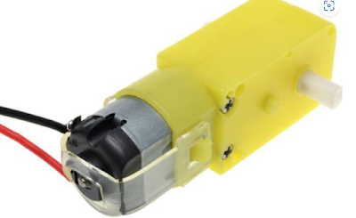
- The black and red wires are soldered to both the yellow DC motors (provided with the chassis) as shown below. The wires are then connected to the M3 and M4 ports of the shield. The polarity of the connections matter, in the sense that if we reverse the connections, the motors will rotate in opposite directions. As a result, our car moves in opposite direction. So we need to first decide which way we want our car to move and then make the connections.
- To know more about the Arduino-L293D stacking and about the motor connections, please refer to video stacking-and-motor-connections. It is a great source of information.

- We mounted both the infrared sensors below the car, such that they will be closer to the ground and hence near the black line. Hence if you see the video, you will not be able to see the IR sensors on top of the car. They get somewhat hidden. We connected Vcc and GND of both the Infrared sensors to +M and GND of the shield respectively.
- We connected the OUT pin of the LEFT infrared sensor to pin 13 of the shield.
- We connected the OUT pin of the RIGHT infrared sensor to pin 2 of the shield.
Before putting the IR sensors to use, we need to calibrate them. Please use the instructions in the site IR Sensor Calibration For Line Follower. This site lists the instructions for line-follower as well as object detection. Make sure you follow the instructions for line-follower. Let me note a couple of points, this site does not mention.
- It mentions making of the connections after the calibration section. However, we have to make sure that we will make the connections, before the calibration. That will help the LED glow based on the potentiometer setting and we can visualize it.
- It mentions the turning ON and OFF of signal LED. However it does not show where the signal LED is located on the IR sensor board. As one might think either one of the black or white LED might be a signal LED. However, that is not the case. The signal LED is placed on the board. It lights ON or OFF based on the placement of the sensor on the white surface or the black line respectively.
We have also used an IR receiver to receive signals from the remote control. Below is a picture for our remote control as well as the IR receiver. Please refer to the video at IR Receiver Connections With Arduino to get the IR Receiver connected with Arduino (in reality the shield) and receive signals from the remote control.


This is the first version of our line follower program. Slowly, we have to modify it in such a way that, we do not see / feel the jerks. The current programming logic is, if the robot is currently on white surface, turn the motors to bring it on black surface. And if it is currently on the black surface, bring it on the white surface. Therefore, the robot moves in a zig-zag manner.
The code for the Line Follower is given below.
We used Arduino IDE to develop the code. line_follower.cpp is the main file, which uses Arduino.h, WProgram.h as built-in libraries those are must for the program to function. The IRremote.h is a library module which needs to be imported for the program to function remotely with a remote control. Now, I will go into the details of only those header files and cpp files which are developed by me. Those are listed above. The line_follower.cpp has the while loop which keeps checking if the STOP button is pressed over the remote control. If the STOP button is not pressed, the car gets the reading from left and right IR sensor. The logic then decides the action to be performed based on the inputs scenarios: There are four distinct scenarios here:
- Left = 1, Right = 1
- Left = 0, Right = 0
- Left = 1, Right = 0
- Left = 0, Right = 1
References
Hope you will also enjoy the article and the video and let me know if you have any questions...
No comments:
Post a Comment